Calibrator 750
precision, clarity, and creative freedom on every pin
Available now in a limited first run!


A foundation for creation
Form Factor & Prototyping Freedom
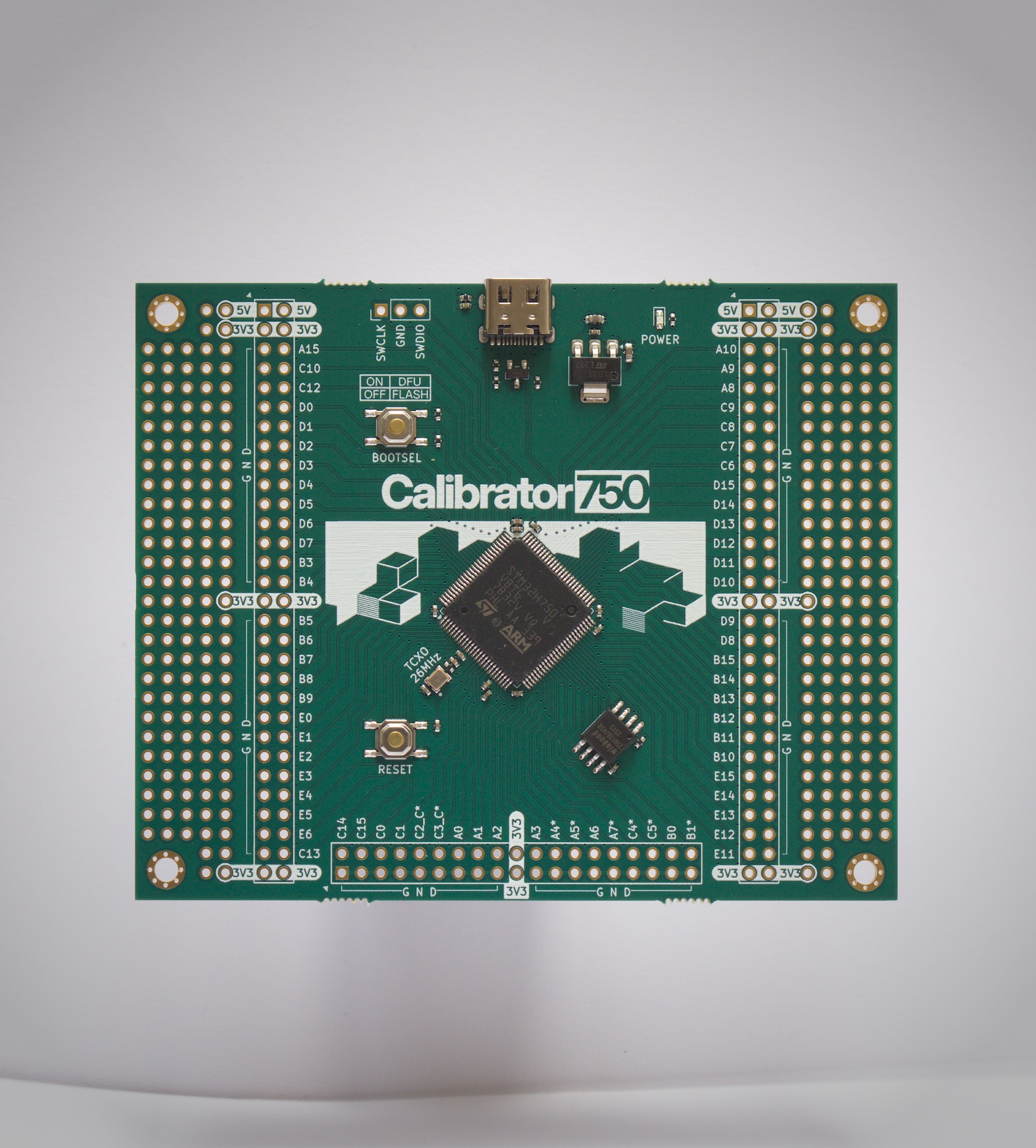
Unlike ultra-mini boards, the Calibrator750 is sized for comfortable two-hand operation. Perforated zones along both sides let you place buttons, encoders, or potentiometers where they feel natural. With compact switches, you can even build a D-pad and assemble a handheld console around the board.
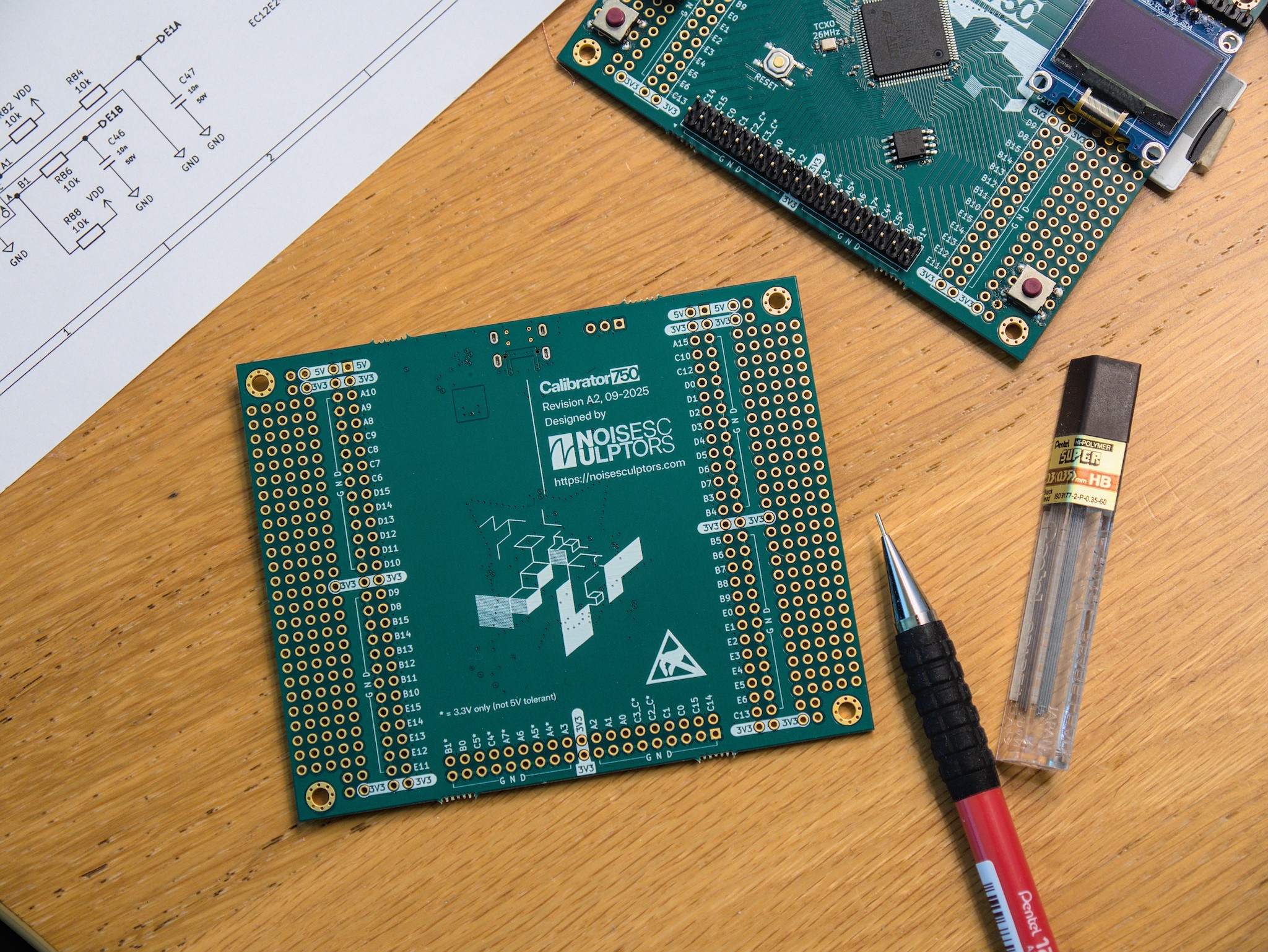
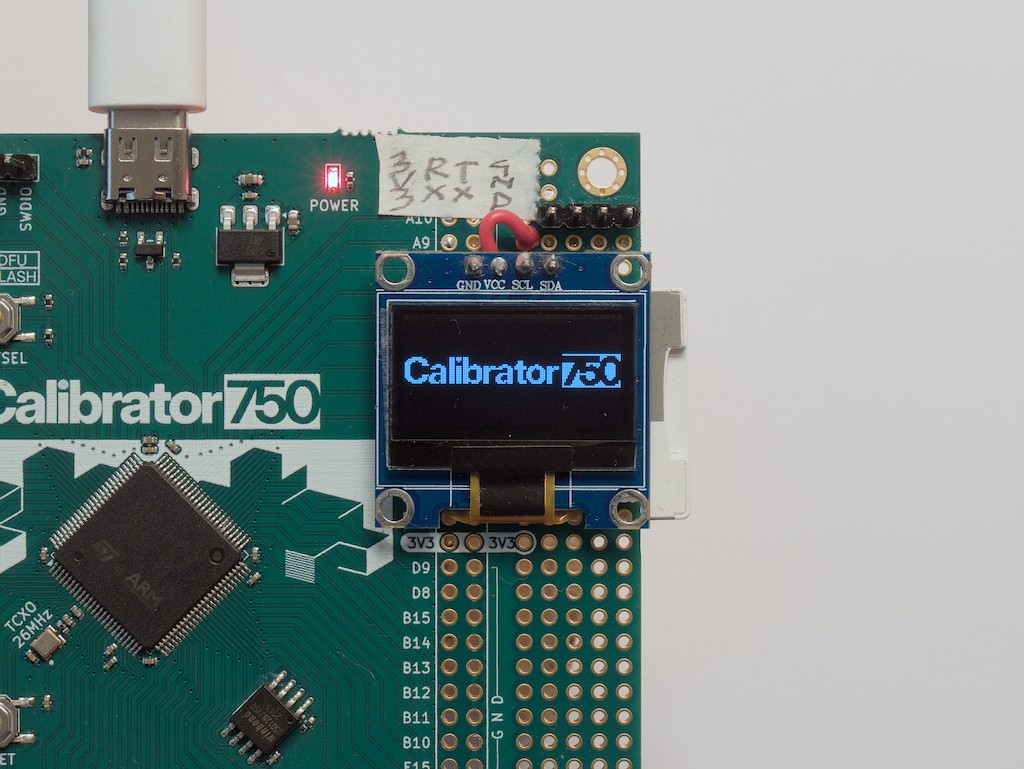
This board gives you a solid foundation without assumptions: no LEDs, no buttons by default — you decide what belongs. Prototyping pads on both sides, so you can add LEDs, sensors, displays, or salvaged components and shape the board to your needs.
It welcomes the odd, the leftover, and the rescued: fit vintage knobs, hand-wired modules, or parts pulled from scrap gear and give them new purpose. What once gathered dust can become your next synth, controller, or experiment.
Performance Headroom
Powered by the STM32H750, the Calibrator750 has room for serious work — real-time DSP, responsive UIs, or retro game engines. Could it run Doom? Of course. The better question is what you will run on it.
GPIOs Paired with Ground
Each GPIO is paired with an adjacent ground pin for clean return paths, low noise, and quick bring-up. Add an LED with a resistor or a push button directly — no breadboard needed. You can even twist signal and ground wires together and plug them side by side for low-impedance, stable connections when adding peripherals or stacking boards.
Not convinced?
Hear it from an expert:“what is the ultimate solution? You give each signal pin its own ground pin, and this way you ensure that the ground return path will always be very short and you have perfect signal integrity and minimum interference.”— Hans Rosenberg, electronic engineer with 30 years of professional experience, YouTube: Why Your Ground Design is WRONG — and How to Fix It (Part 6)

Precision Clocking — 26 MHz TCXO
A temperature-compensated crystal oscillator (TCXO) provides the Calibrator750 with a stable 26 MHz reference that stays accurate across temperature changes and time. Unlike standard crystal oscillators or internal RC clocks, a TCXO continuously adjusts for drift, keeping frequency error within only a few parts per million. This precision benefits every subsystem that depends on timing — from peripheral clocks and timers to serial interfaces and audio sampling. Accurate time bases mean predictable delays, consistent PWM duty cycles, and reliable communication baud rates, even in environments that vary in temperature or supply voltage. Whether you’re running real-time DSP, precise control loops, or communication protocols, the TCXO ensures the entire system stays in sync and stable.
Who Benefits
Makers and developers building instruments, synths, RF circuits, or timing-sensitive tools gain a reliable reference and a layout that encourages fast, hands-on iteration — from quick LED tests to fully customized front panels.
Getting Started with Zephyr
You can download the ready-to-use early release device tree for the Calibrator750 from the Noise Sculptors GitHub and start building right away. Zephyr automatically detects and initializes peripherals defined in the device tree — making it simple to bring your hardware to life.
Hardware Highlights (rev. A2)
- STMicroelectronics STM32H750VB — 32-bit Arm® Cortex®-M7 @ up to 480 MHz; 1027 DMIPS; 128 KB Flash, 1 MB RAM; L1 cache 16 KB + 16 KB; DSP instructions; crypto; rich peripherals.
- Seiko Epson TG-5006CG — 26 MHz Temperature-Compensated Crystal Oscillator (TCXO).
- Winbond W25Q128JV — 128 Mbit (16 MB) SPI / Quad-SPI external flash.
- USB-C Power and Data — powering the board and communicating with the MCU.
- Prototyping Pads — side zones with 3V3, 5V, and GND rails for expansion and experiments.
- Headers with Paired Ground — 72 exposed GPIOs (including SWDIO PA13 and SWCLK PA14); logic-analyzer friendly, stable scope reference beside each signal.
Electrical Characteristics
- Logic levels: 3.3 V logic. Pins marked “*” are 3V3-only; others are 5 V-tolerant for digital input.
- Analog inputs: up to 3.6 V max (do not exceed VDD + 0.3 V).
- GPIO drive: most pins ≈ 20 mA sink/source; low-drive pins C2_C, C3_C ≈ 1 mA; total up to ≈ 140 mA across all I/Os.
- 3.3 V rail: ST LD1117S33; typ. 950 mA output (observe thermal limits for sustained loads).